FT-290R
Table of Contents
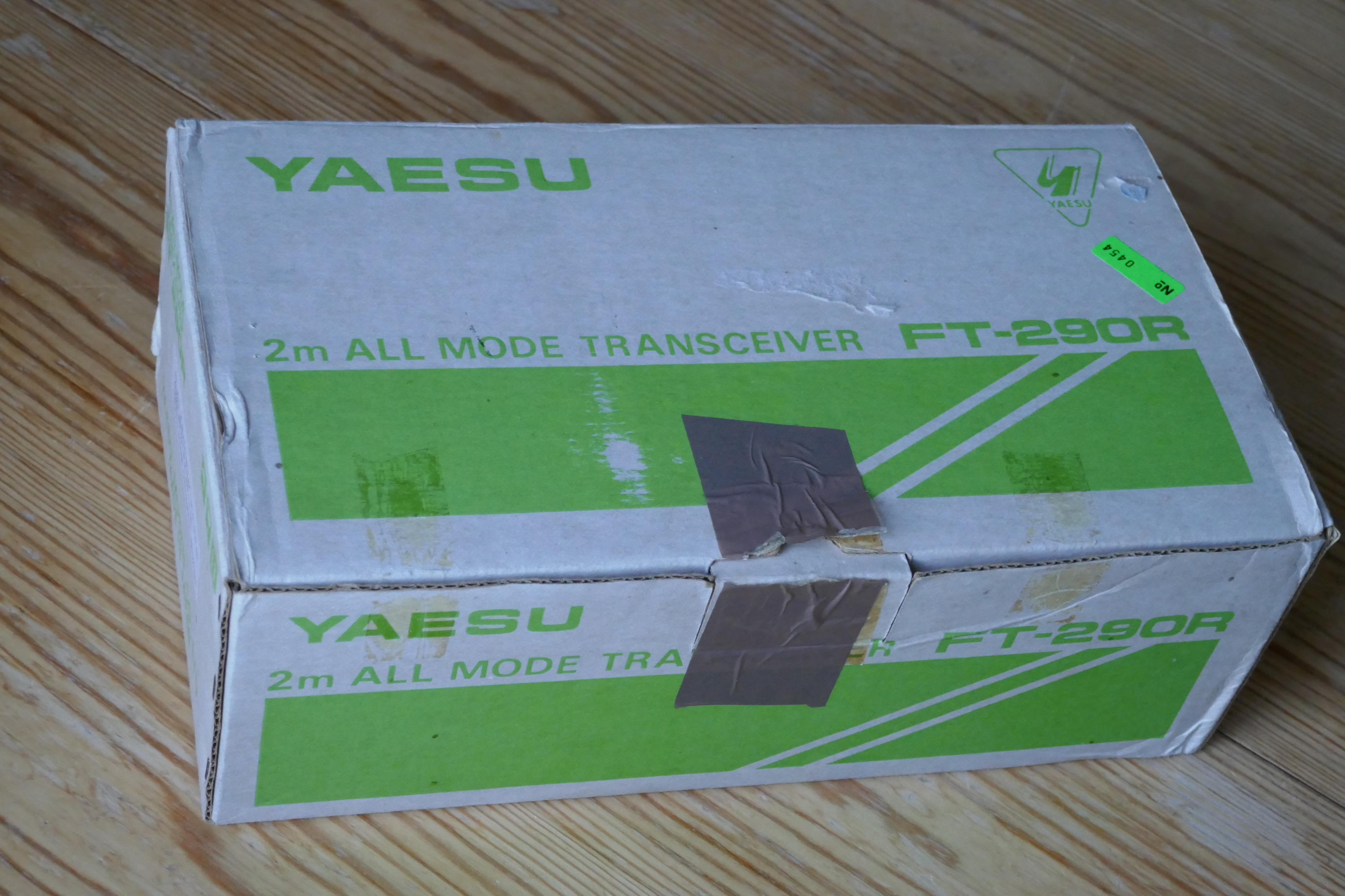
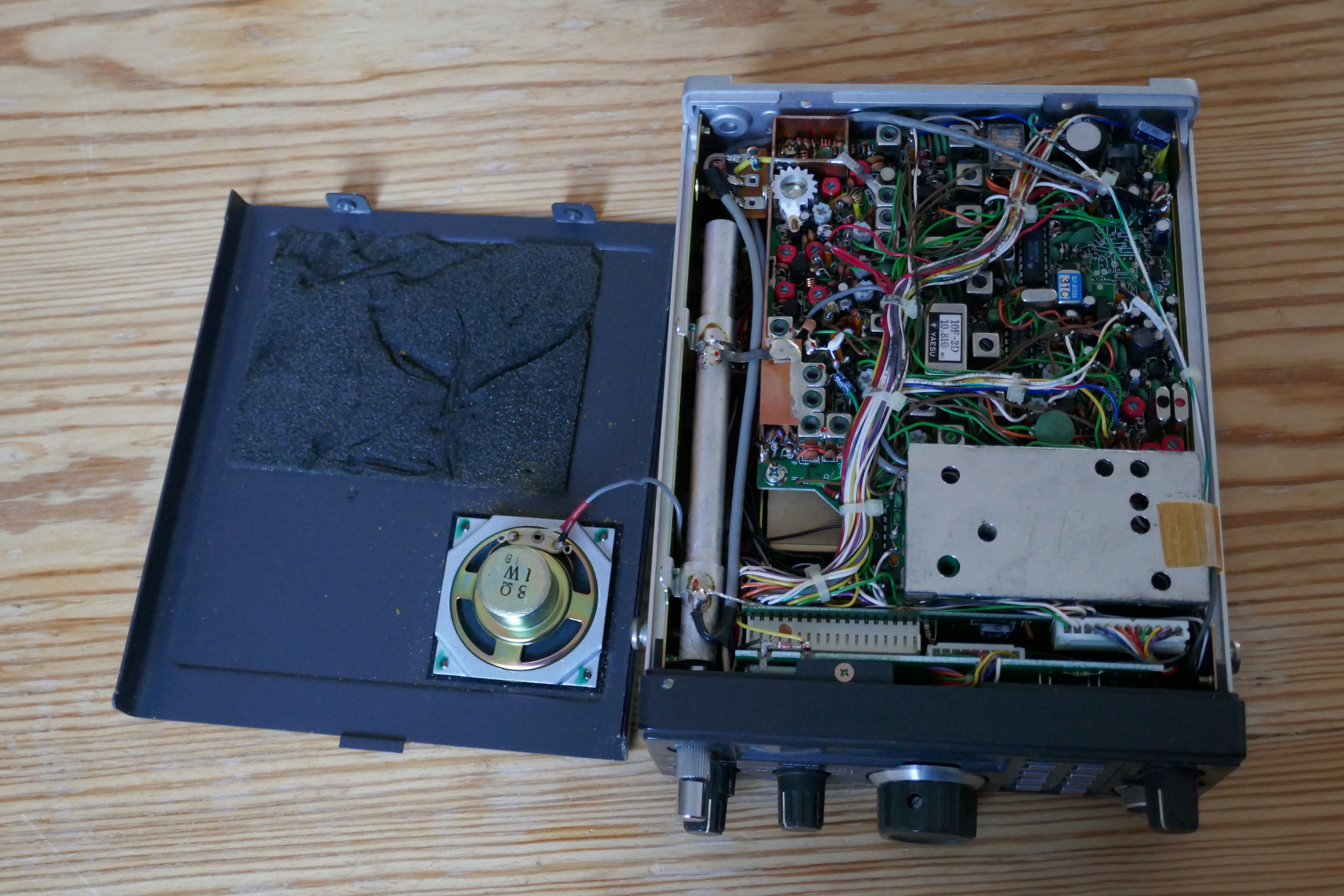
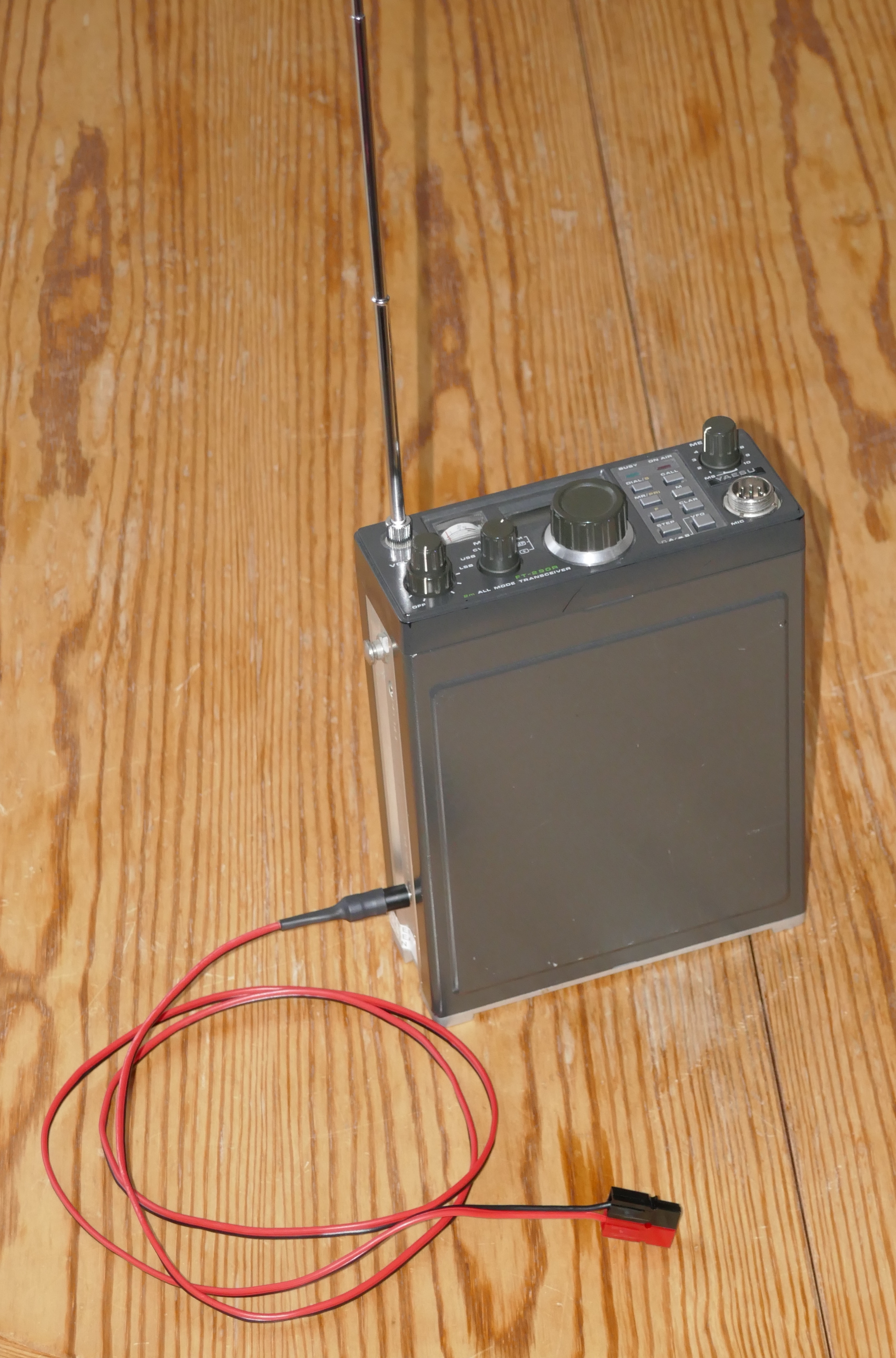
My Yeasu FT-290R (Mk1) all-mode 2mtr tranceiver.
Purchased on 29th December 1983, in Nijmegen, the Netherlands.
A "model B", the "European version" for 144.000…145.999 MHz.
Used, with pleasure, for several years in the Netherlands and the United-Kingdom, until I lost after several house-moves the time and opportunity for the radio-hobby.

((Double?-) Click on diagrams and photos to see an enlarged version.)
Over the years, several web-sites sprung-up around this tranceiver:
- Yaesu FT-290R by ZS1KE
- Mod's, information and glitch fixes for the Yaesu FT-290 MK I by G7COC
- Modifications for the Yaesu FT-290 by some Kiwi (called Scott ?)
- ft290r Universal-Radio
- Reviews for Yeasu FT-290R on eHam side managed by NA4M
- Articles about ft290 on mods.dk
- CTSSS by G4KQK
- Fehlerhafte RX/TX Umschaltung beheben
- Bewährte Modifikationen am FT-290R 2m Band Transceiver(*.pdf Datei) by DB6NT
Feel free to mail me any further related links; see Colophon for my contact details.
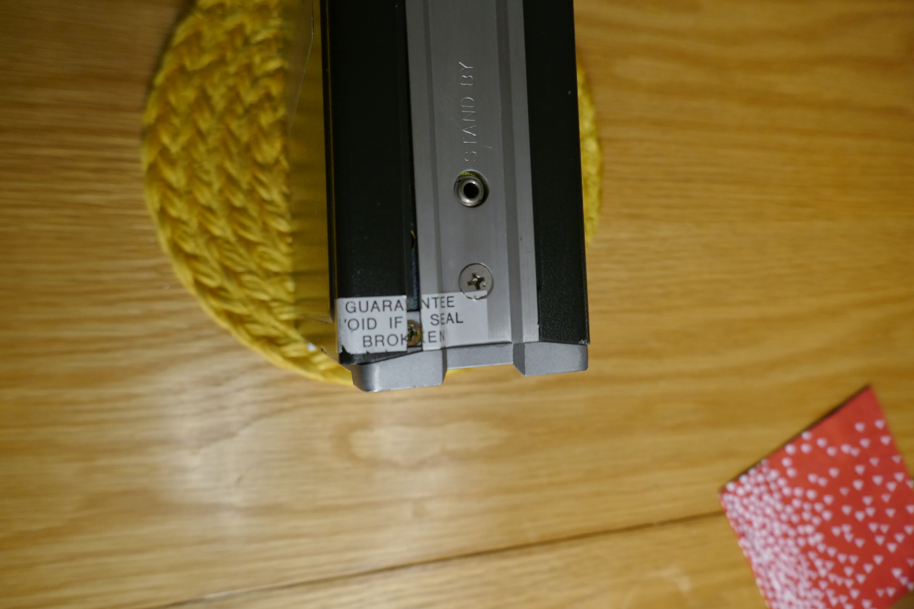
I believe we can ignore this warning by now:
Failure found in 2018
After taking-up the radio-hobby again in 2018, I found that the audio of this device failed.
It was clearly the audio amplifier stage:
- Transmitting clearly functioned.
- Tuning into he local repeater showed activity with the S-meter.
- Both speaker and head-phone output were silent (completely, not even some noise).
It looked like the problem described by G7UVW and others. A replacement of the (u)PC575C2 (Q1027) seemed on the books. Spare chips were already ordered from a web-shop.
Documentation
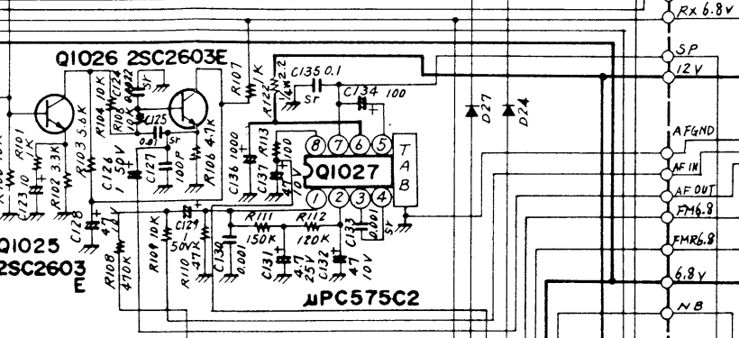
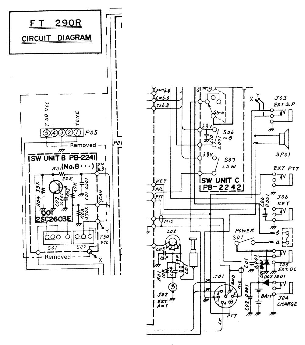
The relevant section of the circuit-diagram:
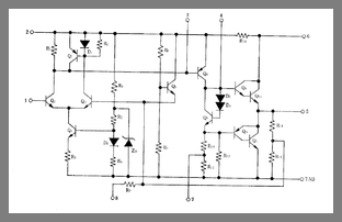
And the internals of that chip:
Diagnosis
Not having much practical experience with this type of work (Solder is not my favorite programming language) I called-in the help of Fred, PE0FKO. He quickly found out that:
- Pin 1 did carry some audio that could be displayed on a scope, and made audible with an external amplifier+speaker.
- Pin 1 carried a DC-voltage of about 0.7V, way too low to open the input transistors.
- Pin 2 carried 12V, as the internal schematic suggest.
- Touching these pins brought the amplifier back to life for a second or so. Suggesting that we discharged an e-cap or so.
- The voltage-divider over R112+R111 and R110 should leave about 1.8V DC on pin 1.
Something was pulling this voltage down, a leaky (or otherwise broken) capacitor, most likely.
- C132? Than pin 2 wouldn't carry the full 12V
- C130? Not an e-cap.
- C131? An ESR-Meter showed an Equivalent Series Resistance of 0Ω. That's the culprit!
The Repair
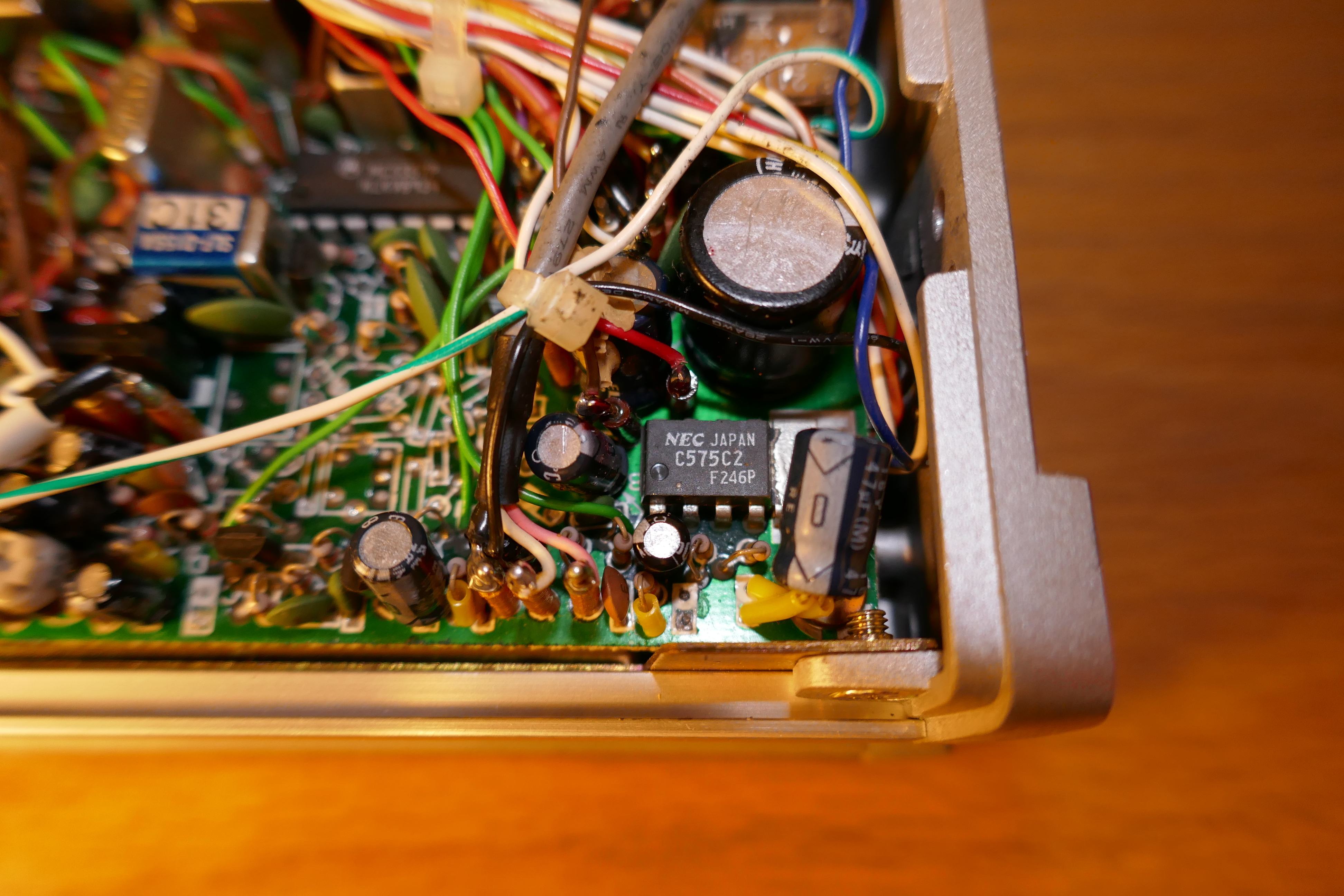
C131 is located close to the PC575C2 at the right-hand-side, rear of the set. It was already removed when these photo's were taken. The capacitor was mounted on the two white squares, right from pins 1&2of the PC575C2, close to the edge of the board.
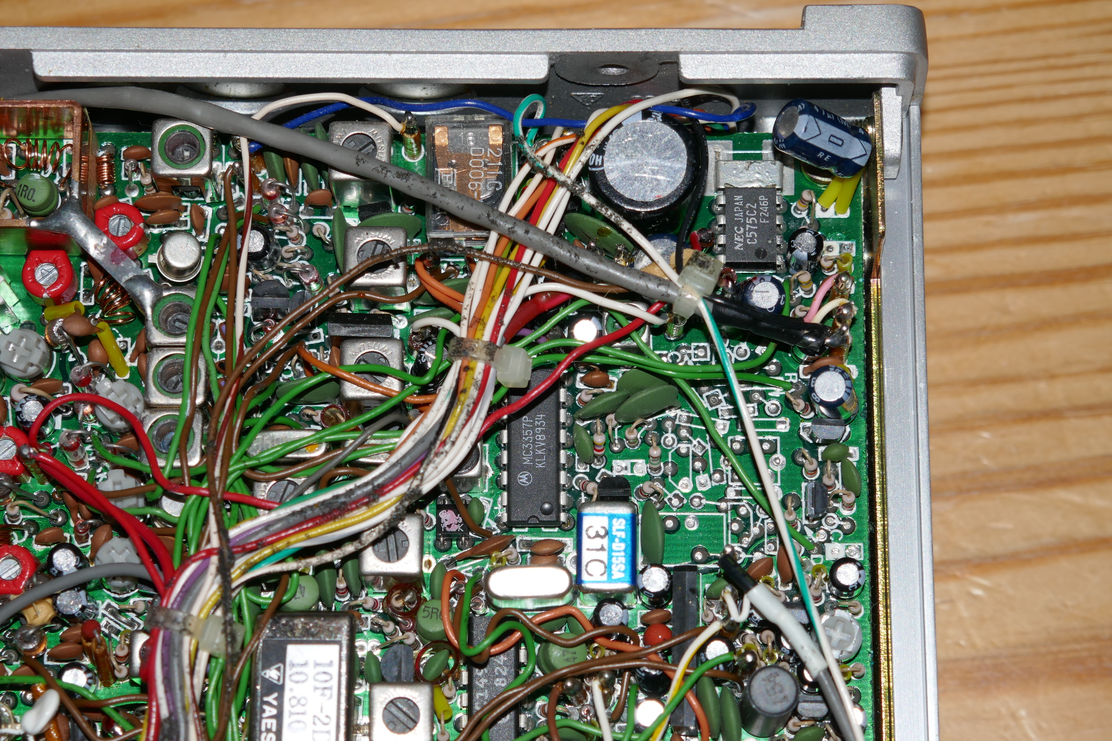
A new capacitor, with the same capacitance of 4.7µF (and a max voltage of 50V, instead of 25V), was soldered in place, but at the rear-side of the PCB.
It is the light-green "blob" just above the center of this photo.
Result
Success ! … Or not … Or, yes, success !
On 1st January 2020 we did receive, and hear!, our own test-signals. This 36 years old tranceiver is functional again!
BUT
During first attempts to use the device "for real", on 4th January 2020, it failed!
Much the same as before. Receiver seems to work, the local repeater moved the S-meter, but no sound out the speaker.
Opened the box, fiddled a bit around, and noticed that the e-cap at the far right, just above the cooling-tab of the PC575C2 was very close to the casing. This visible in the photos above. It is the 47µF capacitor C132. In fact its wires seemed touching the case.
I tried moving the cap back from the casing, over the chip…
AND …
(after re-connecting the power, etc.) the speaker started making noise!
SUCCESS !
First experiences
Antenna wired-up: several stations and repeaters heard; FT8 peeps at 144.174MHz; APRS bursts at 144.8MHz. Not yet an QSO, but heard an echo of my own voice via a repeater.
Frequencies seem reasonably accurate. The memory-backup-battery still has 3V, after all these years! Programming frequencies into memory works and they seem to be remembered. Scanning over the memorized channels works.
Not All is Well
In fact, after powering-up, the audio is for several minutes full of crackles. Only after about 5 minutes these crackles slowly stop and the normal receiver noise prevails. This still suggests that one or more capacitors are faulty.
An scan of all easily visible e-caps did not reveal any that are bulging or otherwise apparently problematic.
Mods, Fixes and Documentation Faults
This careful inspection of the device did show a few other interesting points.
In the late 1980's, early 1990's, some modifications were made to this set. Some I did myself, some were made for my (together with a repair?) and one seems to be a deviation from the schematic by the manufacturer. But, I had forgotten most of it in the years since.
Speaker, Headphone switch.
Apparently, I wanted the possibility to hear audio via the speaker, while there is a plug in the 3.5mm headphone T(R)S socket. This plug was used to connect the FT-290R with a modem and a computer.
I had (as others also described), no use for the Tone-Squelch. So the
Tone-Squelch switch (S02 on the small "switch-unit B") was re-purposed
to bridge the external-speaker-socket (J03), allowing the
builtin-speaker even if a plug is inserted. See the points X and Y.
(As said before: Click on diagrams and photos to see an enlarged version.)
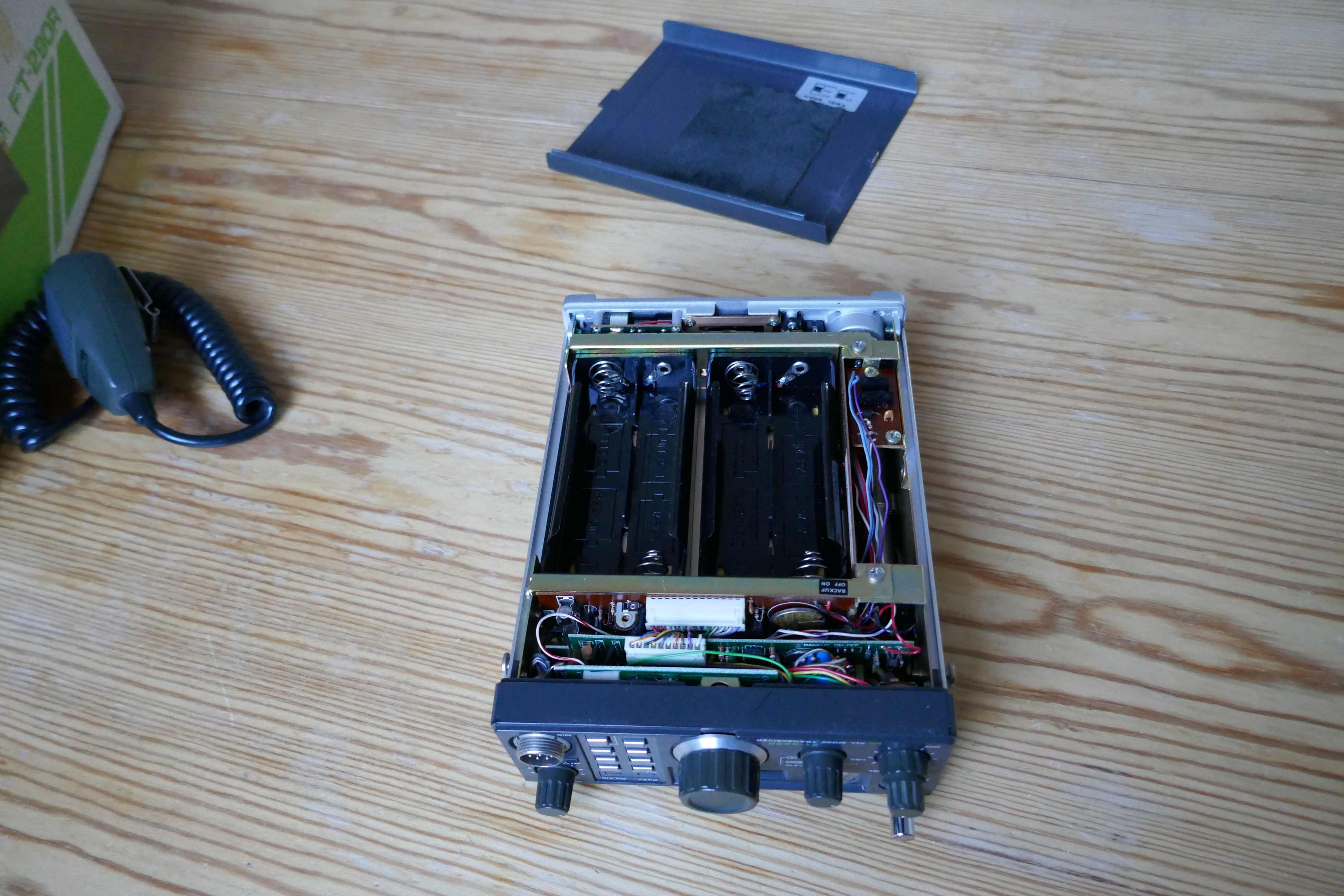
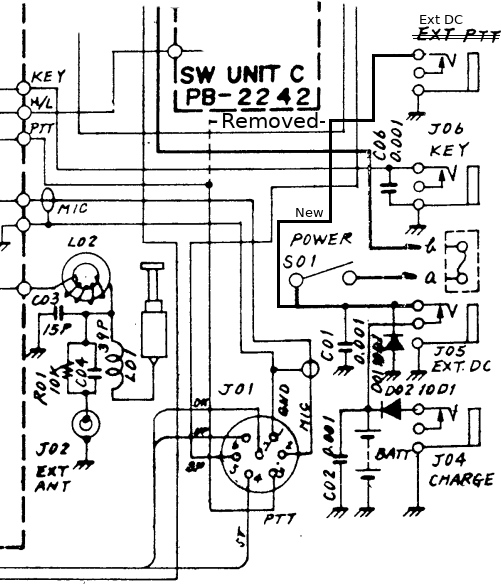
Power Input via a Connector on the Side-panel.
I liked (like) to use the FT-290 standing upright, but powered from an external power-supply. In order to have it standing somewhere, monitoring the local relays and calling channels.
Standing upright was not possible with a power-connector in the "rear apron" (as the manual calls it). On the side panel there is a jack that I never used: The "Stand by" jack, parallel to the microphone PTT switch.
So, I re-purposed this "Stand by" 3.5mm T(R)S jack as an additional external power connection. Plus on he tip, Minus and device-ground on the sleeve; by-passing the funny series diode in the minus-line of the normal power connection (see below). The risk of inverting the power is limited, due to the use Powerpole connectors in most of my 12V cables.
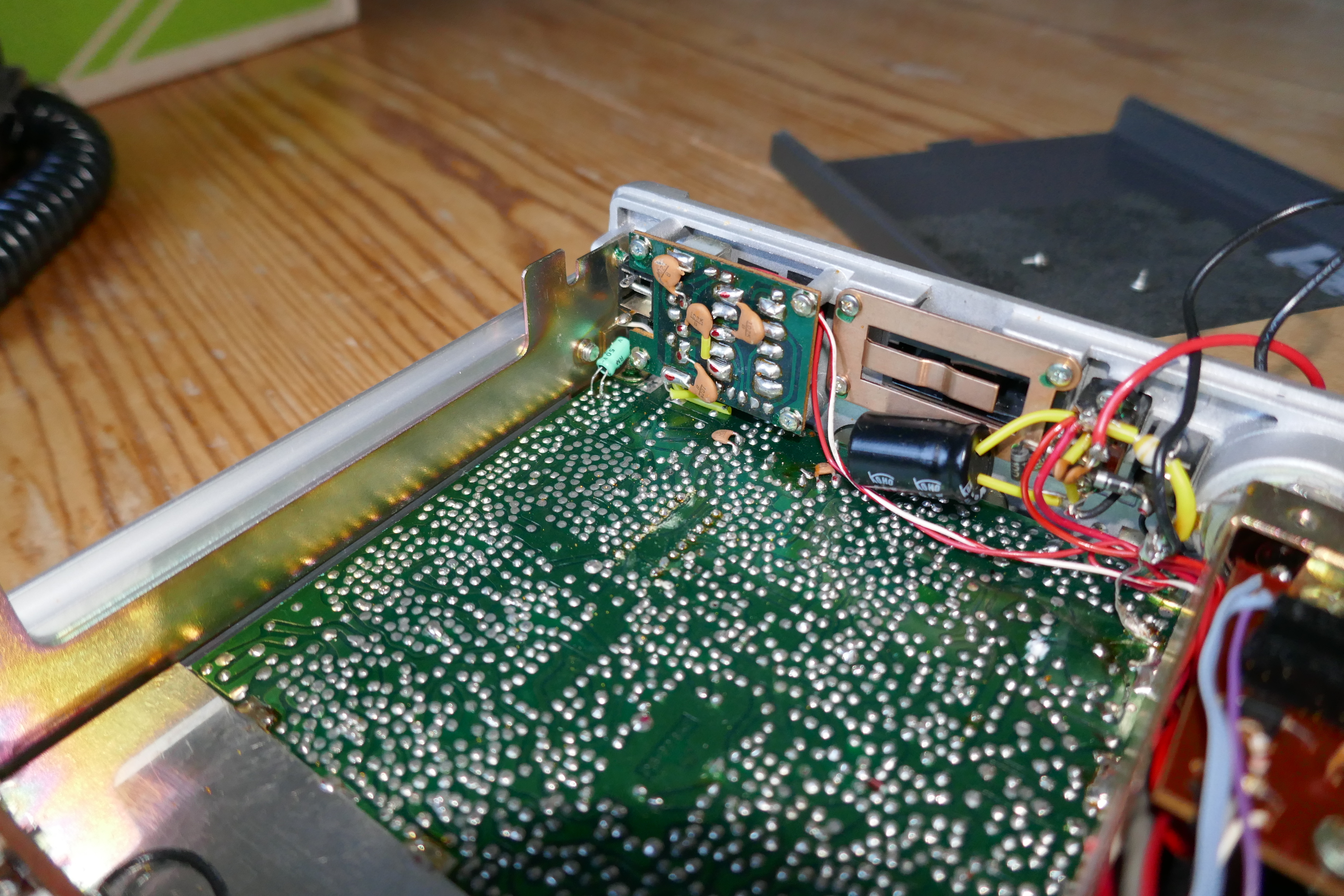
Diode in the Minus Supply Line
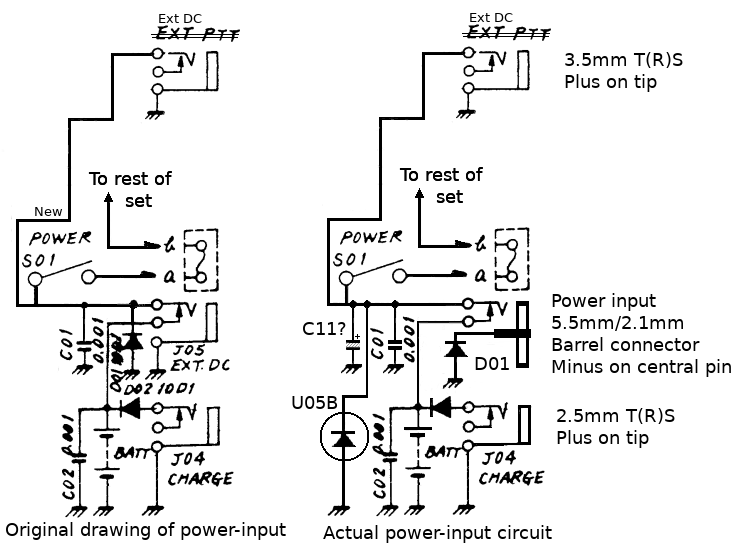
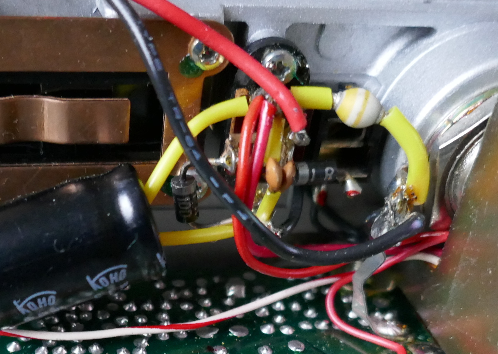
The power-input circuitry on the inside of the rear apron looks different to the circuit diagram.
- Most importantly, diode D01 is wired differently, it is in series with the negative DC power-line, the central pin of the barrel connector. Probably as a protection against inverted power wiring. This protection is of-course easily circumvented if both tranceiver and power-supply are grounded, which is not an unlikely situation in many radio shacks. (I do remember reading about this series-diode somewhere, but I cannot find that article anymore.)
- There is an "extra" electrolytic capacitor. Probably C11 (a 1000µF, 16V e-cap) in the parts list in some on-line versions of the manual; not in the printed manual that I received with the set.
- And there is an "extra" diode that doesn't appear in the diagram, the unmarked yellow/white little bulb in the photo. Probably D04 (an U05B) from the parts list. Also a protection against wiring problems? "Belt and braces!"
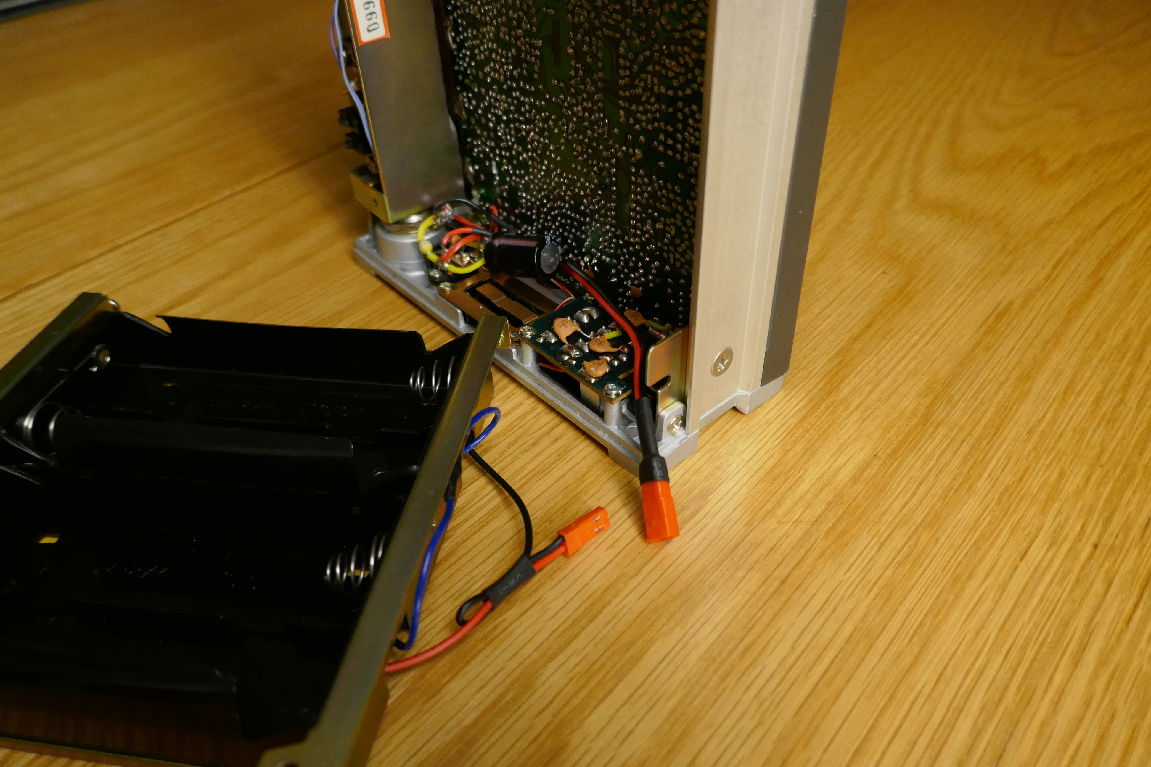
Two current (minor) mods
We can expect to open the device more often, in order to find and replace faulty components. It seemed attractive to include little connectors in the speaker and battery-holder wires. So that these largish things don't hang around close to the device when we operate on it.

First QSO
On Wednesday-morning, 2020-01-15, at 00:20 UTC, the first real QSO in 22+ years was made with this tranceiver. A few members of the local club were still active in FM on 145.550 MHz. Their summary signal report was "Repair Successful!".
Further Experiences
This set has been in regular use since early 2020 as a monitor receiver scanning a few local repeaters and club-channels. In combination with my well-placed 2m antenna, it provides a pretty good coverage of the area.
Quite another, nice, "further experience" is that this little FT290R
web-site is read, on average once a day by people from all over the
world. This in contrast to the other pages of the
pe1aqp and dk1aqp
web-sites; those are seldomly read. Most readers arrive here via the
google search-engine, but with which search-string ? You seem to be
real people: some click on one or two of the photographs.
Lets be clear: You are all very Welcome !
Stay tuned for further reports.